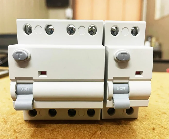
RCCB 10KA- 16A to 63A, 30/100/300mA, DP & FP
Residual Current Circuit Breaker popularly known as Earth Leakage Circuit Breaker (ELCB). The flow of current through electrical facilities always involves risks. Poorly insulated equipment, faulty wires, & incorrect use of an electrical device cause currents to flow through the wrong path. (i.e. through the insulation) to the earth. The current is called ‘Leakage Current’.
Earth Leakage is an electrical hazard and is responsible for electrical shocks and fire risk. Earth leakage and its associated hazard can be prevented by RCCB.
The RCCB works on the current balance principle. The supply conductors, i.e. the phases and the neutral, passed through a torrid and form the primary winding of a current transformer. Its secondary winding is connected to a highly sensitive electromagnetic trip relay, which operates the trip mechanism.
In a healthy circuit, sum of the currents in phases is equal to the current in the neutral and the vector sum of all currents is equal to zero. If there is any insulation fault in the current and leakage current flows to earth, the currents do not balance and their vector sum is not equal to zero. The imbalance is detected by the core balanced current transformer, the RCCB is tripped & supply to load is interrupted. The trip mechanism is operated at a residual current between 50 – 100% of its rated tripping current.
RCCB should be selected based on the connected load or to simplify the matter we can say that the amperage of input MCB can be amperage of RCCB.
As shown on the last slide we have various sensitivities which can affect the human body . So the sensitivity should be selected based on your safety requirements and the condition of the wiring. If the wiring is very old and RCCB is tripping frequently , the wiring should be changed or repaired to achieve The desired results.
| Specifications | IS/IEC 60898-1:2015 |
|---|---|
| Number of Poles | 1, 1+N, 2,3, 3+N &4 |
| Tripping Chara. & Rated Currents (In) | B Curve - 6 – 40 Amp. C Curve - 6 – 63 Amp. |
| Rated Breaking Capacity (lm) | 10000A |
| Energy Limiting Class | Class 3 as per EN 60898 |
| Rated Voltage (Ue) | Single Pole - 240 VAC Multi Pole - 415 VAC |
| Insulation Voltage (Ui) | 660V |
| Rated Frequencies | 50/60 Hz |
| Impulse Withstand Voltage (U imp) | 4 KV (1.2/ 50p) |
| Impulse Power Frequency Voltage | 2 KV (50 Hz) |
| Housing Material | Polybutylene Terephthalate in Grey Colour. |
| Degree of Protection | P20 as per IS/IEC 60898-1 |
| Mounting Position | Any position |
| Mounting | Quick snap to mounting rail - 35 mm |
| Connecting Terminals | Combination box terminals on incoming and outgoing sides. Suitable for Multi core, stranded and flexible conductors up to 35 sq mm. |
| Electrical Service Life | Min. 20,000 make / break operations |
| Ambient Temperature | Tmax 55°C & Tmin. -25°C |
| Impact Resistance | 3g, At least 2 impacts duration 13 ms |
| ISOLATOR | |
| Specifications | IS13947 Part 3 / IEC 60947-3, 1999 |
| Number of poles | DP, TP & FP |
| Utilization Category | AC 22A |
| Rated Voltage | 240/415 VAC |
| Rated Current | 40 to 63 Amp. |
Copyright 2026 Vrix Electric India Pvt Ltd. | Design & Developed By Odmantis Pvt Ltd.
