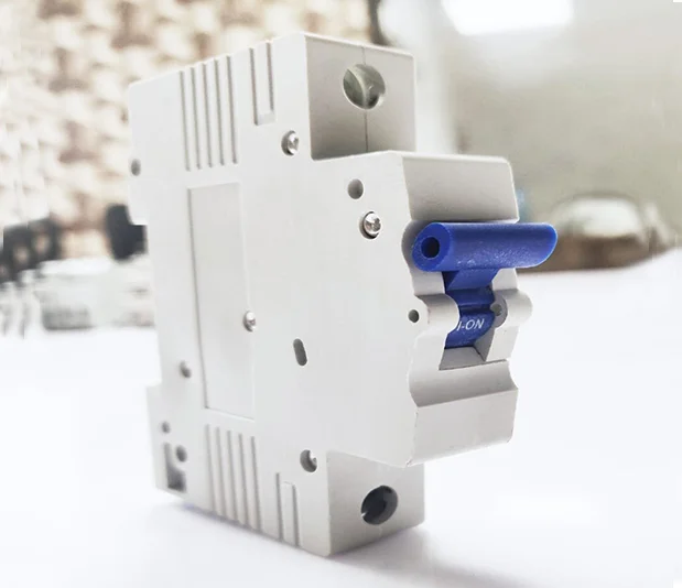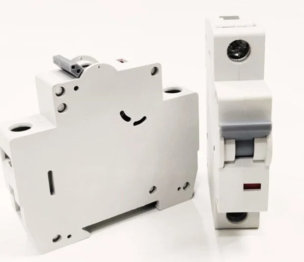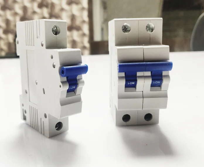
MCB 10kA Centre knob- 0.5A to 63A, B & C Curve, SP/DP/TP/FP/SPN/TPN
Specification IS/IEC 60898-1:2015. Miniature Circuit Breaker is a current operated device. It protects against overload and short circuit fault in electrical supply. The over load protection is achieved with thermal tripping mechanism and short circuit protection is achieved by Magnetic tripping mechanism.
Vrix miniature circuit breakers have precisely formed moulded case & cover of flame retardant high strength thermo-plastic material having high melting point, Low water absorption, high dielectric strength and high temperature withstand. The switch mechanism is independent, manual and trip free, i.e. the breaker trips internally even if the operating knob is held on ON position. The contact mechanism comprises of fixed and moving contacts specially designed for reliability, long life and anti-weld properties. The Arc extinguishing device comprises of 13 plates arc chute. The arc under the influence of the magnetic field and arc guide is move into the arc tripping mechanism which is Thermal magnetic Type.
MCBs have been designed to minimize energy loss through unique contact configuration & reduction of hot spots.
Watt loss per pole in MCB is far lower than that specified in IEC 60898-1.
| Rated Current In | Max. allowable Watt loss per pole as per IS | Max. Watt Loss Per Pole |
|---|---|---|
| 06< In < 10 | 3.0 | 0.70 |
| 10< In < 16 | 3.5 | 2.20 |
| 16 < In < 25 | 4.5 | 2.70 |
| 25 < In < 32 | 6.0 | 3.40 |
| 32 < In < 40 | 7.5 | 4.20 |
| 40 < In < 50 | 9.0 | 4.70 |
| 50 < In < 63 | 13.0 | 5.80 |
| Specifications | IS/IEC 60898-1:2015 |
|---|---|
| Number of Poles | 1, 1+N, 2,3, 3+N &4 |
| Tripping Chara. & Rated Currents (In) | B Curve - 6 – 40 Amp. C Curve - 6 – 63 Amp. |
| Rated Breaking Capacity (lm) | 10000A |
| Energy Limiting Class | Class 3 as per EN 60898 |
| Rated Voltage (Ue) | Single Pole - 240 VAC Multi Pole - 415 VAC |
| Insulation Voltage (Ui) | 660V |
| Rated Frequencies | 50/60 Hz |
| Impulse Withstand Voltage (U imp) | 4 KV (1.2/ 50p) |
| Impulse Power Frequency Voltage | 2 KV (50 Hz) |
| Housing Material | Polybutylene Terephthalate in Grey Colour. |
| Degree of Protection | P20 as per IS/IEC 60898-1 |
| Mounting Position | Any position |
| Mounting | Quick snap to mounting rail - 35 mm |
| Connecting Terminals | Combination box terminals on incoming and outgoing sides. Suitable for Multi core, stranded and flexible conductors up to 35 sq mm. |
| Electrical Service Life | Min. 20,000 make / break operations |
| Ambient Temperature | Tmax 55°C & Tmin. -25°C |
| Impact Resistance | 3g, At least 2 impacts duration 13 ms |
| ISOLATOR | |
| Specifications | IS13947 Part 3 / IEC 60947-3, 1999 |
| Number of poles | DP, TP & FP |
| Utilization Category | AC 22A |
| Rated Voltage | 240/415 VAC |
| Rated Current | 40 to 63 Amp. |
Copyright 2026 Vrix Electric India Pvt Ltd. | Design & Developed By Odmantis Pvt Ltd.